Friday, September 26, 2014

Why You Should Add a Digital Finishing System to Your Business's Workflow


All too often print service providers buy equipment based on what they are producing today instead of looking down the road as to what they may be producing in the future. With the ever increasing capabilities of today's flat-bed and roll printers, the vast array of materials on which graphics can now be printed on require a machine that can digitally finish the process.

No longer are business's in the printing industry buying specific machines for a specific job. Instead, they are seeking a machine that can quickly adapt to their growing productivity needs and provide a solution to their workflow. When companies begin investing in a solution instead of a commodity then the return on investment of both the digital printer and digital finisher begins to grow exponentially. When combined, this partnership of equipment can produce many different products for many different markets resulting in a margin of up to ten times that of producing just one product alone.

The influx of flexibility, as well as increased material savings and control over the production process will allow your business to grow and evolve as new market opportunities arise. Aided with this wider range of capabilities, you will be able to serve a broader market and soon begin reaping the profit potential that comes along with it.

Click HERE for more information on MultiCam's lineup of high-speed digital finishing systems or contact our sales department at sales@multicam.com

Also be sure to stop by booth #2458 at Graph Expo in Chicago, IL 
September 28 - October 1, 2014


Thursday, September 25, 2014

What is the Correct Tool for My Application?

So you’re looking at a sheet of shiny new material and you’ve got your part all mapped out. Your CNC router is ready to go but there’s one thing missing: the proper tool bit. LMT Onsrud, the makers of high quality CNC router bits, have outlined a series of questions that need to be answered before the best bit for the job can be selected. These questions are ones that we ask our customers every day so that we know we’re recommending the tool that has the ideal size, flute, and rigidity requirements.

First, what type of material is being machined?

This is the first and most basic question because it defines the type of tool material and geometry needed to perform the job. In terms of wood, some are natural woods; others are man-made composites or combinations of both. Plastic and aluminum have characteristics of hardness and softness, which dictates tool material and geometry. Consequently, the foremost question becomes how is the part material going to affect the tool material and the life of the tool?

What type of router is being used?

The use of a hand router or pin router dictates different tool choices than a CNC machine. The obvious difference is feed and speed capabilities and how various tool materials react in the cutting environment. Hand fed operations tend to be best suited to steel bodied router tools, which can better tolerate inconsistent feeds, while CNC machines enhance the toughness of solid carbide.

What is the material thickness?

Quite simply, this question leads to the selection of tool diameter and cutting edge length. Always choose the tool with the shortest possible cutting edge to cover the thickness of the part with slight overlap. Since diameter of tool increases rigidity, it is best to select the largest diameter possible, but the cutting edge length should be as short as possible and not more than three times the diameter (in a perfect world).

What is the part configuration?

The size, contour and detail in a part play a huge role in tool selection and tool life. For instance, large parts can be machined extremely fast and may react very well with a multi-flute tool. Conversely, a smaller part with tight radii would operate ineffectively with multi-flute tools by decreasing tool life because of slower feed and speed.

How is the part being held?

Tool selection is almost a moot issue if the part is not held solidly. MultiCam recommends a vacuum hold-down system for your CNC router or knife cutter. This ensures that both the material and the part stay still, increasing the tool life and the accuracy of the cut.

What influence should the tool have on the part?

Router tools come in straight, shear, spiral downcut, and a combination of up and down cut. They come in single flute through multi-flute in a wide range of diameters. All these characteristics have an influence on the part. For example, in a thermoformed part which is set up on a formed fixture, it is important to have no or neutral influence on the part to alleviate problems of pulling the part off the fixture. The larger diameter tools exert more lateral pressure on a part; smaller diameters do the opposite but provide less chip removal because of smaller flute area. Spirals move chips up or down and influence the part in the same direction. Influencing the part by tool selection is important and must be considered when selecting the right tool.

What is the most important consideration, speed or finish?

The selection on feeds and speeds specifically details the theory behind chiploads and tool life. Once the right tool for a job is chosen, the tool life is really a function of how the end-user fixtures the part and the speed and feed rate applied to the part. If chips are produced a significant thickness to dissipate heat, then tool life will be extended.
In summary, following these basic principles will aid in the tool selection process:
  • Match the tool with material and the application
  • Select a tool with shortest cutting edge length to cut through the part
  • Select the largest diameter possible to achieve rigidity
  • Keep cutting and shank diameter the same whenever possible
  • Select tools that accomplish the goal i.e. finish or speed
  • Select tools on the way the part needs to be influenced
  • Select multi-function tools i.e. compression spiral with mortise point
  • Select tools based on productivity rather than cost

For all your tooling needs and recommendations please contact our sales department at sales@multicam.com or call us 972.929.4070

You can also shop online at store.multicam.com

Friday, September 12, 2014

FridayCutFacts: How to Use a Router to Cut Aluminum for Sign Letter Fabrication.

If you are looking to prevail in the sign industry where flexibility and versatility are necessary for a business to succeed, then adding a reliable CNC router to your workflow is a no-brainer.

Whether you are working with wood, foam, or acrylic a CNC router can help generate the superior products that customers envision. But one question we are frequently asked by manufacturers is "Can your routers cut aluminum as well?" Our answer is always a resounding, "Yes! As long as you do it correctly."

There are a few things know about cutting aluminum on a router before you begin. First, like all materials, there is a "Sweet Spot" for the best feeds and speeds. When cutting aluminum, the "Sweet Spot" is much smaller, and the chances for breaking a bit and outputting a poor surface finish are increased. Secondly, aluminum heats up and becomes sticky when cutting, so if you venture outside of the "Sweet Spot" aluminum deposits will begin to weld themselves to your tooling or your cut piece.

To help you visualize the "Sweet Spot" for speeds and feeds of cutting aluminum, take a look at the chart below.

Here is a breakdown of the different zones in the graph.

High Chipload Feed: When your feedrate is too fast for a given spindle RPM, you're chances of breaking the bit are almost certain.
MRR: Running the spindle as fast as you can without burning the bit and feeding as fast as you can without breaking the bit is the "Sweet Spot" for Maximum Removal Rates.
Too Fast: Too much spindle speed will generate excess heat which softens the tool and dulls it faster. 
Best Tool Life: Slowing down the spindle a bit and feeding at slightly less than appropriate for maximum MRR gives the best tool life. 
Surface Finish: Reducing your feedrates while keeping the spindle speed up lightens the chipload and leads to a nicer surface finish. There are limits, the biggest of which is that you'll eventually lighten the feedrate too much, your tools will start to rub, and tool life will go way down due to the excess heat generated by the rubbing.
Older Machines: So your spindle speed has come way down, and in addition, so has your feedrate. You're probably on an older machine where you can't run the kind of speeds you need to take advantage of carbide tooling. You may need to switch to HSS. 
Feeding Too Slow: Feeding too slow leads to rubbing instead of cutting, which can radically shorten your tool life and is to be avoided.

PUTTING IT TO THE TEST:

When cutting 6061 1/8 inch aluminum for sign letter fabrication we used a 63620 Stub Nose 1/4 inch Up-Cut Bit at 22,000 RPM and at speed of 100 in./min.
Multicam Cutting Aluminum

Multicam_Aluminum1

 HELPFUL TIP: Be sure to use a lubricating mist to cut down on the tendency for the chips to stick to the cutting edges. The optional mister on thisMultiCam 3000 router provides both an air blast and a coolant mist.
Multicam_Aluminum2

Notice how these chips aren't too flaky! They are exactly what you want to see when cutting aluminum. Its a good sign that your feeds and speeds are in the "Sweet Spot". At 22,000 RPMs, the chips produced were hot enough to transfer the heat to the chips instead of the finished piece or the tooling.

multicam_aluminum3

Here is our finished piece. As you can see cutting aluminum is entirely possible with a CNC router. It's just a matter of matching your machines capabilities to the "Sweet Spot" feeds and speeds of the material. 

multicam_cnc_aluminum4

VISIT MULTICAM.COM

Tuesday, September 2, 2014

TuesdayTips: Creating Images with EnRoute Rapid Picture


One of the truly unique applications offered by EnRoute software is its Rapid Picture technology. Rapid Picture is an extension of Rapid Texture that allows you to import your favorite photograph as a bitmap image, and apply contours that translate into the contrasting shades of the photograph.

Below is a step by step process of how we easily created an image on 3/4 inch MDF using our 3000 Series MultiCam Router.

Step 1:
First we applied a coat of white semi-gloss paint to our MDF board.

Step 2:
Next, we coated the painted board with a high-gloss sealer. This will allow you to easily apply a contrasting color once the image has been cut. It will also allow you to apply a smaller gap value and prevent any paint being chipped during the engraving process.

Step 3:
Open EnRoute and import your desired .JPG or Bitmap image. High contrast images usually work best.

Step 4:
Select your line tool and draw a line across the picture. The direction of the line will determine the direction of the contours being cut. We opted to draw our line diagonally.

Step 5:
With your contour line selected click on the rapid texture icon (highlighted below).

Step 6:
Enter the size values of the image you want to cut then click on the displacement tab. Here you will enter your Wavelength, Offset, and Horizontal and Vertical Amplitude Values.

We used a wavelength of 3 and an offset and horizontal/vertical amplitude of .15. You might have to play around with these values depending on the image you would like to cut.

Step 7: 
Make sure randomize is unchecked then before you hit apply, click on the picture. Here you will be prompted to select your tool and enter the gap value.

For this image we suggest using a 90 degree conic with a gap value of .01.

Step 7:
Hit apply and EnRoute will automatically begin to create the contours of the image.

Step 8: 
Once the contours have been applied you can set your feed, speeds and depths.
The values we used for the piece were:
Feed Rate - 300, Speed - 18000, Depth - .1, Plunge Rate - 100

Step 9:
Export your .DXF file and CUT IT!

Step 10: 
Experiment and enjoy! You might want to play with the values a bit to determine what will work best for your image.

If you are really looking to make the image pop, water down some black paint and apply it to the contours that were cut. Once you wipe off the excess paint you will be left with an almost photo realistic image carved into your material.


Visit MULTICAM.com


Friday, August 22, 2014

FridayCutFacts: How to Get a Mirror Like Edge Quality When Cutting Acrylic

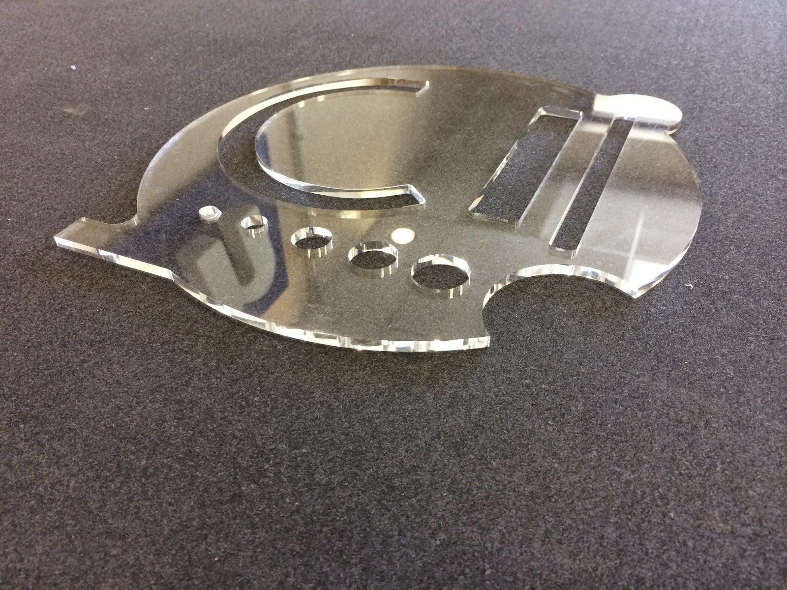
When cutting acrylic for applications where the edge will be visible and will need to be either polished or at least very smooth, it's absolutely imperative that you get the cut right the first time. So, today we put our new 6mm Crown Norge Diamond bit to the test and were blown away by the results. 

For our initial cut pass we used a 1/4 inch Super Upcut Bit on 1/4 clear acrylic at a feed rate of 150 in./min. and a speed of 28000 RPM's. 

To get the perfect edge quality we needed, the 6mm Diamond Bit performed 2 passes at 20 in./min. and 30000 RPM's. 
6mm Diamond Bit
MultiCam 3000 Router Polishing Acylic
To achieve the best results and avoid the rewelding of acrylic dust we recommend monitoring the polishing passes and removing any dust that is created. 

The final results:


Visit MULTICAM.COM


Monday, August 18, 2014

Monday's Make: Fishbone Chair out of 3/4 inch MDF

In anticipation for the upcoming IWF Show in Atlanta this week we decided to test our furniture making skills with this Fishbone Chair design. It is a simple design that can easily be found online or created using your favorite CAD/CAM program.

For this project we used our MultiCam 3000 Router to cut 3/4 inch MDF. We used a 3/8 upcut bit  at a speed of 24000 RPM and a federate of 600 in./min.


Go to MULTICAM.COM

Friday, July 25, 2014

Halftone Dot Art Sign sample

Happy Friday!

We created a bear sign out of dots with our 3000 Series Router and plastic material.
There are over 15,000 dots used to create this bear. The process is a bit lengthy, taking about a total of six hours, but it results in a very interesting piece of art.