Monday, December 29, 2014

4 Trends in Woodworking for 2015


Both Cabinet Maker FDM and Woodworking Network have come out with their predictions and trends to be on the lookout for in 2015. Here we present a few of these trends that are of particular interest:
Investments in New Technology
The president of the Cabinet Makers Association, Matt Krig, is expecting many woodworking shops to finally make the leap into new technologies, or to replace their aging equipment. “Most CMA members are optimistic,” he says. “A lot of guys bought a lot of things at the show (IWF) and are at the point of making significant investments (in new technology).” Not only are they projected to invest in capital equipment, but woodworkers are predicted to expand their product in knowledge in plastics and other non-wood products. The demand for mixed medium projects, especially in the housing market, is on the rise and shops are adapting.
With the increased popularity of cable networks such as HGTV, many customers are becoming more demanding when it comes to projects. They want shorter project times and lead times. Matt Krig also notes that there could also be a skilled labour shortage as those companies investing in technology require employees that are trained.
Lumber prices
Wood prices on the riseIn an interview with Cabinet Marker FDM, Gene Wengert, a wood technologist and a consultant to the woodworking industry, sees an interesting convergence of trends that will likely lead to higher lumber prices in the coming year. The lumber industry faces a shortage of sawmills and logging crews because many went out of business during the recession. “A third of them are gone,” says Wengert. But then there is another factor that most in the woodworking industry might not think about. “The big one is the tremendous need for railroad ties,” says Wengert.
He explains that the increase in domestic oil production fueled by shale oil development and fracking has increased the need for fuel transport by rail since there are not enough pipelines. That will increase the financial incentive for existing sawmills to saw more lower grades of lumber for railroad ties, which will create a shortage of those grades in the general lumber stream.
“The price will go up in all grades,” says Wengert. “We may have a 50 percent increase. We have to learn to be more efficient then we are now so we create less waste.” Companies will need to put more emphasis on how lumber is cut and graded, as well as confirming they are being supplied with the right grades and footages. “When you check grades and board footage, it’s amazing how often it is off,” he says.
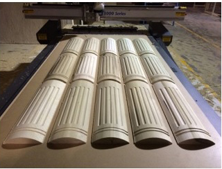
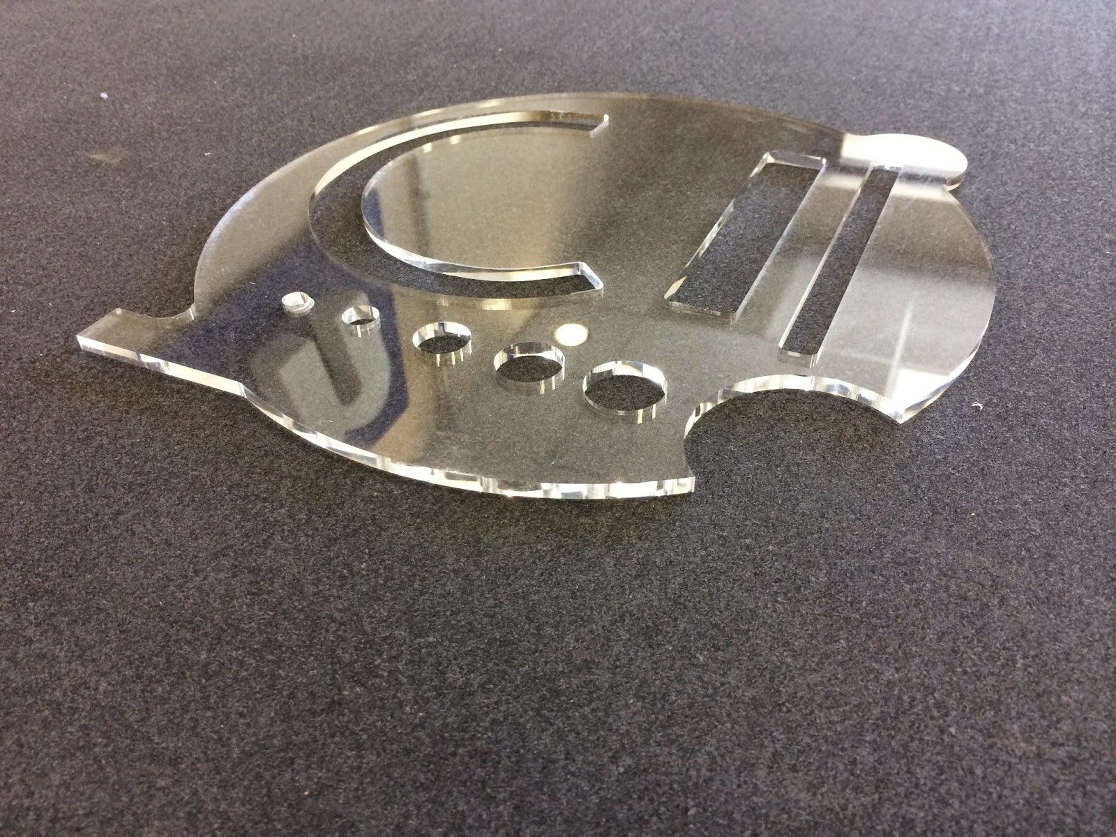
5-axis routing5- Axis Routing
According to the Woodworking Network, the latest developments in advanced CNC machining centres have made 5-axis technology more accessible to the average woodworking shop. With the lines continuing to blur between CNC routers and CNC machining, 5-axis technology on a point-to-point router, for example, can give woodworkers the ability to manufacture high-precision and complex shapes and components. (If you’re interested in 5-axis, might we suggest checking out our 8000 Series Router).
Reshoring
As with many industries, reshoring activities in the woodworking and furniture making industries is estimated to continue. According to the Woodworking Network Almanac, 15% of new US manufacturing jobs between 2010 and 2013 were previously overseas. A stronger economy, the inflation of foreign currency, and a boom to the North American housing market have all contributed to companies choosing to manufacture on this continent, rather than look abroad.

Friday, December 5, 2014

MultiCam Celebrates 25th Anniversary


MultiCam Inc., a leading manufacturing of CNC cutting solutions, is pleased to announce that the end of 2014 will round out its first quarter century of operation. Since opening its doors in December of 1989, MultiCam's products have become an integral part of the manufacturing industry, advancing technology and value into systems that are highly productive, easy to use and built to last.

MultiCam Inc., originally Machine Automation Technology, was founded by Ken Koelling who began building complete CNC systems customized to the needs of his customers. His main goal was to ensure that every machine was engineered to perfection, built with passion and remained reliable for the life of the machine. He instilled a value equation into the company that ensured that the products built exceeded the industrial standards of the marketplace, yet remained affordable to small businesses around the globe.

Today, MultiCam has manufactured and installed more than 10,000 machines worldwide transforming Koelling's vision into a globally recognized, industry leader. "We continue to stand behind the goals and principles set forth 25 years ago," said Kelsey Smith, Marketing Director of MultiCam Inc. "Exemplary customer satisfaction, employee fulfillment and corporate citizenship remain the cornerstones of this company. Sustained success in these areas, we believe, will continue to yield long-term benefits for our brand, employees and our partners."

Tuesday, November 18, 2014

The State of Plasma

In the wake of an economic downturn and recovery, plasma - like the manufacturing industry as a whole  -  needs to change and adapt. To find out what particular challenges the industry's facing as it seeks to do so, we talked to Hypertherm's president, Evan Smith.

FAB Shop: What's the state of the plasma industry right now?

Smith: Well, when I think about the plasma market, I tend to think about it as part of the steel fabrication or steel cutting industry more broadly. The wider steel fabrication capital equipment market is generally healthy, but it's mixed by global region and by industry. And now that we're past the Great Recession, and also the immediate recovery, it's kind of a more mixed economic environment for investment and fabrication equipment. The decision makers are still cautious.

We're seeing equipment usage up. There's evidence by consumable demand, but I'd say that with the actual demand for equipment itself, we still see a fair amount of postponement in the industry. Light industrial demand is up, but the investment threshold is also lower.

Out of the three technologies -  plasma, waterjet and laser -  waterjet is probably the strongest right now, but plasma is holding onto its share in the product marketplace.

FAB Shop: What challenges do you see the plasma industry needing to overcome as it moves forward?

Smith: Like with most cutting technologies, there's the skilled workforce shortage. We find a lot of end users operating sub-optimally, so there are the issues of operator training and system optimization. A lot of end users are unaware of technology upgrade opportunities, too.

I think also, for plasma in particular we see automation and material handling being an area of less development. Plasma is by far the most productive and cost-cutting technology available for most high-volume plate cutting applications. But in terms of overall automation, we see that further development needs to be made there.

FAB Shop: What would you say that development will entail?

Smith: Well, naturally, the development focuses on the cutting process itself. So, for example, it would mean making plasma cutting faster, more cost effective, higher quality, more precise and so forth. We also see a lot of development need being in the software, in the control and in the whole upstream and downstream process integration with the actual cutting.

FAB Shop: How else to you see the plasma industry needing to change and adapt over the coming years?

Smith: I think more application focus versus system focus is going to be an important requirement, as well as focusing increasingly on service levels and advisory relationships, which will help customers address the issue that I mentioned earlier, of operating sub-optimally and not being aware of the technology and the upgrade potential. I think we'll also see more flexible in-sourcing and outsourcing among customers, and more emphasis on total lean operations.

In building those customer relationships, I think we'll need to go beyond the equipment or system performance itself and increasingly look at life cycle for the customer, in order to gain an understanding of what they're trying to accomplish in their applications. This way, we'll be able to deliver those particular applications in better and better ways.

I think other fields in the steel fabrication industry are simply more connected and smarter in terms of software and automation development. They're able to address the issues of self-monitoring and self-optimization, and thus also the shortage of skilled workers.

Plasma needs to follow suit. In the near future, I would expect that plasma systems will be more connected, perhaps through the cloud, and more application optimized. Broader application capabilities will allow plasma to enter new spaces that have been previously dominated by other cutting technologies. And following the trend of digital factory, the plasma system itself will provide more information and intelligence into total factory management systems and processes.

Right now, as an example, Hypertherm controllers can monitor certain parameters of system performance and often allow remote connectivity through the Internet. This is how we facilitate the information flows to partners and to Hypertherm in order to allow value added services.

FAB Shop: To summarize, where do you see the plasma industry in five years?

Smith: Well, its a little bit like the last 20 years. Certainly, plasma technology will continue to improve. It will increase in speed and precision, have a better cut quality , be more repeatable and have a lower cost per foot or linear cut, but I think you're also going to see an expanded application space for plasma as we continue to push particular adaptations and optimizations of the technology.

I would expect to see smarter and more connected machinery, as we've discussed -  machines that are self-monitored and more able to operate without human intervention.

We're also pushing greener technology, and we think the industry and equipment will become cleaner and greener in terms of its footprint and its impact on the environment.

I think we'll see systems -  as we've talked about - with increasingly more sophisticated software and and control technology. The plasma system itself will become more integrated for particular application, and we'll have more embedded process intelligence. And as process intelligence evolves, we'll probably see self-teaching or self-learning systems.

FAB Shop: Thank you.

For more information on MultiCam's lineup of versatile CNC  Plasma Cutting Machines visit www.multicam.com/plasmas.html

Article from FAB Shop Magazine.


Friday, November 7, 2014

Spindle, Toolholder Hygiene Checklist

Cleaning the toolholder
Article by Nicholas J. Korfias, found in Shop Metal Tech Magazine.

8 Tips to maintain toolholder-machine spindle interface accuracy

A minute chip floating in coolant swarf left to dry on a toolholder taper can become a serous interference at the machine tool spindle-toolholder interface. It can go undetected, causing slightly increased cutter runout(TIR) and diminished tool performance at low spindle speeds. At higher spindle speeds, the negative effects are magnified and can result in scrapped parts, catastrophic failure and a possible accident.
A contamination-free toolholder and machine tool spindle interface ensures toolholders properly seat at full taper contact and are pulled into the spindle taper at maximum force. With holders held and positioned accurately, a machine’s full power and tolerance capabilities can effectively and safely transfer to cutting tools, while runout and vibration are reduced for superior part surface finish quality.
The following are eight simple tips for maintaining toolholder-machine spindle interface accuracy and integrity.
1. Shops should clean and inspect toolholders and spindles after every job. Toolholders should be completely disassembled and cleaned. Today’s’ synthetic and semi-synthetic coolants can leave surfaces gummy, causing chips and other contaminants to easily adhere to them. Machine spindles should be cleaned and visually inspected before being returned to service. An oil-dissolving cleaner can be used to clean coolant residue from tollholer and spindle surfaces.
2. Spindle cleaning should be done as part of the overall machine breakdown routine that happens after every job.
3. Dust-free cloths or paper towels with light penetrating oil and manual wiping tools work best for cleaning the spindle socket surface. Most manual wiping tools feature helical cleaning blades set at angles matching those of a machine tool’s spindle. Once surfaces are cleaned, they should be sprayed with a  coat of light penetrating oil to prevent rusting.
4. Shops should use a “ForceCheck” device to check their machine spindle’s puling power on a quarterly basis. This practice should be employed as a preventative maintenance procedure, with results recorded and tracked. Any sudden drops in pulling force from one quarter to the next can indicate a potential issue with the spindle system and can provide early detection for preventing catastrophic failure.
5. If possible, a tool crib manager of designated tooling person should manage toolholder maintenance. As jobs are completed and tools are returned to the crib, cutters and holders should be completely disassembled and all components cleaned manually or in an ultrasonic system, then reassembled. Ultrasonic cleaning system quickly and efficiently clean toolholder tapers, collet cavities, holder nuts, collets and all the other smaller sub-assembly holder parts.
6. If toolholder tapers show visual signs of wear, manufacturers suggest running them through an automatic powerbrush wiping system that uses rotating tapered brushes. After doing so, holers should be cleaned in a n ultra sonic cleaning system, wiped clean and sprayed with a coating of light penetrating oil.
7. Once spindles and toolholders have been cleaned, a visual inspection should be made of the surfaces. They should be free of any defects. If serious damage is found in a spindle interface surface, a professional may be needed to re-grind the spindle taper socket. Damaged toolholder or machine spindle surfaces left dirty or unrepaired will, in turn, damage other tool and machine spindle mating surfaces.
8. Once tooling has been cleaned and properly maintained, store it to avoid any re-contamination as it moves from tool crib or tool cart to machine tools. Surface rust can occur while tools are stored, so they should always be sprayed with a coat of light penetrating oil. Shops should only load clean tool holders into machine spindles and automatic tool changing (ATC) systems. Again, dirty or damaged toolholder surfaces can easily transfer imperfections to other toolholders and onto machine spindle surfaces.

If your toolholders or spindles have reached the end of their useful life, visit out store at store.multicam.com or call us 972-929-4070 and order a replacement right away!

Friday, October 31, 2014

This Carpenter's Spirit Lives On Through His Machine


In 1968, a man by the name of Alejandro de la Cruz Saucedo started a small family wood shop in the town of Jesus Maria, Mexico. With only a handmade circular saw and the premise of "Making Furniture with Conviction", Alejandro set out to create incredible works of Rococo style furniture characterized by the superior French craftsmanship of the 18th-century.

For over 45 years now, Mueblera Provenzal has been producing outstanding results in fine furniture and has become a pioneer of the furniture industry in the Municipality of Jesus Maria.

Ever since he first witnessed the amazing abilities of CNC manufacturing, Alejandro made clear his dream of one day adding a CNC Router to his shop, now located in a 60,000 sq. ft. facility in the center of San Antonio de los Horcones in Jesus Maria.

Sadly, Alejandro passed away recently and was unable to see his dream come true by his own eyes. After his death, Alejandro's wife set out to make his dream become a reality and honor his life long commitment to the company, his town and his family.

Last month, with much anticipation, Mueblera Provenzal welcomed their brand new MultiCam 3000 Router to their work shop and paid homage to the man they revered so much.

Check out these pictures from the installation ceremony!

MultiCam 3000 Router
MultiCam 3000 Router Machine

MultiCam 3000 Router Machine


Wednesday, October 22, 2014

How To Optimize the Cut Quality of Your CNC WaterJet With SigmaNEST

Feedrate edge qualities in waterjet cutting
In CNC WaterJet cutting, when we refer to the feedrate, we’re talking about how fast the waterjet moves along the material per minute. The faster the waterjet moves, the more quickly it will cut the material, but with increased taper. The slower the waterjet moves, the slower it will cut, but the edge quality with greatly improve. Optimizing cut quality with operational efficiency is a balancing act between desired cut quality, material type/thickness, and abrasive feedrate.
When a waterjet moves more slowly over a piece, more water and abrasive is able to erode the material, thus increasing the cut quality. However, the more abrasive you use, the higher your operating costs will be. Many operations will average about 0.7lbs/min of abrasive. When it comes to operating costs, the amount of abrasive used in waterjet cutting is the single largest contributor. It is therefore important to ensure that you’re only using the absolute minimum amount of abrasive that you need for your cut.
To do this, think about the type of cut you’re trying to achieve. Do you require a very smooth cut, with perfect edge quality and negligible taper? Or perhaps you require merely a separation cut, where the edge quality isn’t nearly as important. SigmaNEST has a very simple way of choosing the level of cut quality you require for your job. This is an especially handy tool when your part does not require the same level of quality on all sides.
Feedrate control for waterjetMerely click on the cut line in the dashboard and click on the quality tab. This will allow you to choose from 1 (fastest cut speed, separation cut quality) to 5 (slowest cutting speed, smoothest edge). Having greater control over the quality you choose for each edge on your part means that you’re not wasting abrasive (and operating time), when a lower quality cut could do the job just as effectively.
Proper feed rate control for waterjet cutting is just another way that SigmaNEST software helps you not only cut better, but smarter.

Wednesday, October 8, 2014

What Are The Key Functions of a Plasma Electrode?

With today’s long-life oxygen cutting technology, CNC plasma systems are the most productive, cost effective way to cut carbon steel from gauge to 1 1/4” thickness. But to get the highest performance, operators need to ensure the consumables in the torch are inspected and maintained to high standards. To do that, a good understanding of the features and functions of each consumable is paramount to getting the most out of your machine.

The primary function for a plasma electrode is to provide power to the plasma arc, connecting to the negative output from the power supply. The plasma electrode’s secondary function is to conduct high voltage (aka, high frequency) energy during the starting sequence, adding energy to ionize the cutting gas, thus allowing the plasma arc to start. Since the electrode is the main contact point for the plasma arc, it gets very hot. As a result, the end emitter on an oxygen electrode, made of the element hafnium, can reach temperatures exceeding 3000 degrees F. In general, most plasma cutting electrodes used at over 100 Amps of cutting current are liquid cooled, as opposed to gas cooled in smaller mechanized and hand held plasma systems.hafnium emitter in plasma electrode
So what are the plasma electrode’s critical features? First of all, the hafnium emitter is the single most important part for the electrode. Since hafnium is a poor thermal conductor, it is bonded to the copper body of the electrode using a proprietary process that ensures an excellent thermal and electrical connection. Hypertherm electrodes use a patented process that matches the diameter of the hafnium emitter to the power level it is designed for, ensuring the most efficient heat transfer. Another very important factor to ensure cut quality is repeatable dimensional stability, where the electrode fits up well to the other internal torch components. If you have the incorrect length or diameter it will dramatically affect alignment and impact the cutting quality.
hollow milled post in plasma electrodeThe second critical feature for the plasma electrode are the very accurately machined bore and step, which insure superior cooling as a result of perfect alignment of the coolant tube to the hollow milled post in the electrode bottom. As well, alignment can provide for very concentric coolant flow around the high temperature hafnium emitter.
locating shoulder on plasma electrodeAll Hypertherm electrodes have a laser etched part number and a batch code clearly marked to ensure proper part match-up. And the threads and locating shoulder are designed to ensure perfect concentricity with nozzle and swirl ring when installed in the torch.
coolant tube around plasma electrode
Finally, the key feature of both the electrode and torch design is a floating coolant tube. How does the floating coolant tube work? The tube is loosely installed in the torch and when the electrode is installed the coolant tube self aligns and positions itself to the internal features of electrode. The coolant enters at the top of the tube at relatively high pressure and is forced through a tight fit around the hollow mill of the electrode. In the end, the squeeze increases coolant velocity, effectively causing the coolant to strip away steam buildup around the hot hafnium, for very efficient heat removal.

For a one stop shop of all your consumable needs, be sure to drop by the MultiCam Store today!


Thursday, October 2, 2014

What Does Modern Manufacturing Really Look Like?

MultiCam CNC Machines

The vast majority of American's today have a very skewed outlook of what modern manufacturing really is. We often recollect images of rough, down trodden workers slaving away in hot, miserable conditions for hours on end until they are freed by the sound of the whistle.

Ask any student today, "Would you rather work for a manufacturing company or a tech company?" Most, if not all will answer the latter. Why? Because tech is cool. Tech is smart. Tech creates images of clean facilities with endless possibilities of grander and prosperity.

But what if I was to tell you that the coolest, most technological company in the world is, at its heart and soul, a manufacturing company.

When we talk about Apple the story that gets lost is, at the end of the day they manufacture products. The iPad, iPhone and Macintosh didn't just come to be with the snap of a finger. These products are the end result of taking intellectual ideas and figuring out a way through processes and technology, how to build somebody's idea.

With more and more factories complaining about a shortage of skilled workers and baby boomers
retiring at a rate of nearly 10,000 a day, there has never been a more important time in our history to raise awareness among the young and expose them to what modern manufacturing really is, and more importantly, what it isn't.

Tomorrow is National Manufacturing Day and I challenge everyone from students to educators to legislators and citizens from every community to take part. Go into that manufacturing facility that you have driven passed thousands of times on your way to work or to school and take a look at what is really going on inside.

When you do, you will see an environment that is innovative and technology driven. There is engineering, math and science. You will find a place where all of these things come together to make great products.

MultiCam CNC Table
In terms of all the geopolitical events taking place around the world right now, it is definitely in our nation's best interest to be able to have manufacturing capabilities. We need to be able to attract people to pursue these careers and to be interested in starting a manufacturing business and to seek all the options and opportunities that manufacturing provides.

To learn more about MFG Day visit www.mfgday.com 


Not able to make it to one of the events? "How It's Made" will be running an all day marathon on the Science Channel Friday Oct. 3rd. This is a great way for families to introduce their children, maybe for the first time, to what manufacturing is and what it's about.

Witness the innovation, the technology, the smarts and the bright people responsible for making the products we use. 

Friday, September 26, 2014

Why You Should Add a Digital Finishing System to Your Business's Workflow


All too often print service providers buy equipment based on what they are producing today instead of looking down the road as to what they may be producing in the future. With the ever increasing capabilities of today's flat-bed and roll printers, the vast array of materials on which graphics can now be printed on require a machine that can digitally finish the process.

No longer are business's in the printing industry buying specific machines for a specific job. Instead, they are seeking a machine that can quickly adapt to their growing productivity needs and provide a solution to their workflow. When companies begin investing in a solution instead of a commodity then the return on investment of both the digital printer and digital finisher begins to grow exponentially. When combined, this partnership of equipment can produce many different products for many different markets resulting in a margin of up to ten times that of producing just one product alone.

The influx of flexibility, as well as increased material savings and control over the production process will allow your business to grow and evolve as new market opportunities arise. Aided with this wider range of capabilities, you will be able to serve a broader market and soon begin reaping the profit potential that comes along with it.

Click HERE for more information on MultiCam's lineup of high-speed digital finishing systems or contact our sales department at sales@multicam.com

Also be sure to stop by booth #2458 at Graph Expo in Chicago, IL 
September 28 - October 1, 2014


Thursday, September 25, 2014

What is the Correct Tool for My Application?

So you’re looking at a sheet of shiny new material and you’ve got your part all mapped out. Your CNC router is ready to go but there’s one thing missing: the proper tool bit. LMT Onsrud, the makers of high quality CNC router bits, have outlined a series of questions that need to be answered before the best bit for the job can be selected. These questions are ones that we ask our customers every day so that we know we’re recommending the tool that has the ideal size, flute, and rigidity requirements.

First, what type of material is being machined?

This is the first and most basic question because it defines the type of tool material and geometry needed to perform the job. In terms of wood, some are natural woods; others are man-made composites or combinations of both. Plastic and aluminum have characteristics of hardness and softness, which dictates tool material and geometry. Consequently, the foremost question becomes how is the part material going to affect the tool material and the life of the tool?

What type of router is being used?

The use of a hand router or pin router dictates different tool choices than a CNC machine. The obvious difference is feed and speed capabilities and how various tool materials react in the cutting environment. Hand fed operations tend to be best suited to steel bodied router tools, which can better tolerate inconsistent feeds, while CNC machines enhance the toughness of solid carbide.

What is the material thickness?

Quite simply, this question leads to the selection of tool diameter and cutting edge length. Always choose the tool with the shortest possible cutting edge to cover the thickness of the part with slight overlap. Since diameter of tool increases rigidity, it is best to select the largest diameter possible, but the cutting edge length should be as short as possible and not more than three times the diameter (in a perfect world).

What is the part configuration?

The size, contour and detail in a part play a huge role in tool selection and tool life. For instance, large parts can be machined extremely fast and may react very well with a multi-flute tool. Conversely, a smaller part with tight radii would operate ineffectively with multi-flute tools by decreasing tool life because of slower feed and speed.

How is the part being held?

Tool selection is almost a moot issue if the part is not held solidly. MultiCam recommends a vacuum hold-down system for your CNC router or knife cutter. This ensures that both the material and the part stay still, increasing the tool life and the accuracy of the cut.

What influence should the tool have on the part?

Router tools come in straight, shear, spiral downcut, and a combination of up and down cut. They come in single flute through multi-flute in a wide range of diameters. All these characteristics have an influence on the part. For example, in a thermoformed part which is set up on a formed fixture, it is important to have no or neutral influence on the part to alleviate problems of pulling the part off the fixture. The larger diameter tools exert more lateral pressure on a part; smaller diameters do the opposite but provide less chip removal because of smaller flute area. Spirals move chips up or down and influence the part in the same direction. Influencing the part by tool selection is important and must be considered when selecting the right tool.

What is the most important consideration, speed or finish?

The selection on feeds and speeds specifically details the theory behind chiploads and tool life. Once the right tool for a job is chosen, the tool life is really a function of how the end-user fixtures the part and the speed and feed rate applied to the part. If chips are produced a significant thickness to dissipate heat, then tool life will be extended.
In summary, following these basic principles will aid in the tool selection process:
  • Match the tool with material and the application
  • Select a tool with shortest cutting edge length to cut through the part
  • Select the largest diameter possible to achieve rigidity
  • Keep cutting and shank diameter the same whenever possible
  • Select tools that accomplish the goal i.e. finish or speed
  • Select tools on the way the part needs to be influenced
  • Select multi-function tools i.e. compression spiral with mortise point
  • Select tools based on productivity rather than cost

For all your tooling needs and recommendations please contact our sales department at sales@multicam.com or call us 972.929.4070

You can also shop online at store.multicam.com

Friday, September 12, 2014

FridayCutFacts: How to Use a Router to Cut Aluminum for Sign Letter Fabrication.

If you are looking to prevail in the sign industry where flexibility and versatility are necessary for a business to succeed, then adding a reliable CNC router to your workflow is a no-brainer.

Whether you are working with wood, foam, or acrylic a CNC router can help generate the superior products that customers envision. But one question we are frequently asked by manufacturers is "Can your routers cut aluminum as well?" Our answer is always a resounding, "Yes! As long as you do it correctly."

There are a few things know about cutting aluminum on a router before you begin. First, like all materials, there is a "Sweet Spot" for the best feeds and speeds. When cutting aluminum, the "Sweet Spot" is much smaller, and the chances for breaking a bit and outputting a poor surface finish are increased. Secondly, aluminum heats up and becomes sticky when cutting, so if you venture outside of the "Sweet Spot" aluminum deposits will begin to weld themselves to your tooling or your cut piece.

To help you visualize the "Sweet Spot" for speeds and feeds of cutting aluminum, take a look at the chart below.

Here is a breakdown of the different zones in the graph.

High Chipload Feed: When your feedrate is too fast for a given spindle RPM, you're chances of breaking the bit are almost certain.
MRR: Running the spindle as fast as you can without burning the bit and feeding as fast as you can without breaking the bit is the "Sweet Spot" for Maximum Removal Rates.
Too Fast: Too much spindle speed will generate excess heat which softens the tool and dulls it faster. 
Best Tool Life: Slowing down the spindle a bit and feeding at slightly less than appropriate for maximum MRR gives the best tool life. 
Surface Finish: Reducing your feedrates while keeping the spindle speed up lightens the chipload and leads to a nicer surface finish. There are limits, the biggest of which is that you'll eventually lighten the feedrate too much, your tools will start to rub, and tool life will go way down due to the excess heat generated by the rubbing.
Older Machines: So your spindle speed has come way down, and in addition, so has your feedrate. You're probably on an older machine where you can't run the kind of speeds you need to take advantage of carbide tooling. You may need to switch to HSS. 
Feeding Too Slow: Feeding too slow leads to rubbing instead of cutting, which can radically shorten your tool life and is to be avoided.

PUTTING IT TO THE TEST:

When cutting 6061 1/8 inch aluminum for sign letter fabrication we used a 63620 Stub Nose 1/4 inch Up-Cut Bit at 22,000 RPM and at speed of 100 in./min.
Multicam Cutting Aluminum

Multicam_Aluminum1

 HELPFUL TIP: Be sure to use a lubricating mist to cut down on the tendency for the chips to stick to the cutting edges. The optional mister on thisMultiCam 3000 router provides both an air blast and a coolant mist.
Multicam_Aluminum2

Notice how these chips aren't too flaky! They are exactly what you want to see when cutting aluminum. Its a good sign that your feeds and speeds are in the "Sweet Spot". At 22,000 RPMs, the chips produced were hot enough to transfer the heat to the chips instead of the finished piece or the tooling.

multicam_aluminum3

Here is our finished piece. As you can see cutting aluminum is entirely possible with a CNC router. It's just a matter of matching your machines capabilities to the "Sweet Spot" feeds and speeds of the material. 

multicam_cnc_aluminum4

VISIT MULTICAM.COM

Tuesday, September 2, 2014

TuesdayTips: Creating Images with EnRoute Rapid Picture


One of the truly unique applications offered by EnRoute software is its Rapid Picture technology. Rapid Picture is an extension of Rapid Texture that allows you to import your favorite photograph as a bitmap image, and apply contours that translate into the contrasting shades of the photograph.

Below is a step by step process of how we easily created an image on 3/4 inch MDF using our 3000 Series MultiCam Router.

Step 1:
First we applied a coat of white semi-gloss paint to our MDF board.

Step 2:
Next, we coated the painted board with a high-gloss sealer. This will allow you to easily apply a contrasting color once the image has been cut. It will also allow you to apply a smaller gap value and prevent any paint being chipped during the engraving process.

Step 3:
Open EnRoute and import your desired .JPG or Bitmap image. High contrast images usually work best.

Step 4:
Select your line tool and draw a line across the picture. The direction of the line will determine the direction of the contours being cut. We opted to draw our line diagonally.

Step 5:
With your contour line selected click on the rapid texture icon (highlighted below).

Step 6:
Enter the size values of the image you want to cut then click on the displacement tab. Here you will enter your Wavelength, Offset, and Horizontal and Vertical Amplitude Values.

We used a wavelength of 3 and an offset and horizontal/vertical amplitude of .15. You might have to play around with these values depending on the image you would like to cut.

Step 7: 
Make sure randomize is unchecked then before you hit apply, click on the picture. Here you will be prompted to select your tool and enter the gap value.

For this image we suggest using a 90 degree conic with a gap value of .01.

Step 7:
Hit apply and EnRoute will automatically begin to create the contours of the image.

Step 8: 
Once the contours have been applied you can set your feed, speeds and depths.
The values we used for the piece were:
Feed Rate - 300, Speed - 18000, Depth - .1, Plunge Rate - 100

Step 9:
Export your .DXF file and CUT IT!

Step 10: 
Experiment and enjoy! You might want to play with the values a bit to determine what will work best for your image.

If you are really looking to make the image pop, water down some black paint and apply it to the contours that were cut. Once you wipe off the excess paint you will be left with an almost photo realistic image carved into your material.


Visit MULTICAM.com


Friday, August 22, 2014

FridayCutFacts: How to Get a Mirror Like Edge Quality When Cutting Acrylic

When cutting acrylic for applications where the edge will be visible and will need to be either polished or at least very smooth, it's absolutely imperative that you get the cut right the first time. So, today we put our new 6mm Crown Norge Diamond bit to the test and were blown away by the results. 

For our initial cut pass we used a 1/4 inch Super Upcut Bit on 1/4 clear acrylic at a feed rate of 150 in./min. and a speed of 28000 RPM's. 

To get the perfect edge quality we needed, the 6mm Diamond Bit performed 2 passes at 20 in./min. and 30000 RPM's. 
6mm Diamond Bit
MultiCam 3000 Router Polishing Acylic
To achieve the best results and avoid the rewelding of acrylic dust we recommend monitoring the polishing passes and removing any dust that is created. 

The final results:


Visit MULTICAM.COM